Ring Design Introduction
Smalley Spirolox Retaining Ring and Constant Section Ring applications, although diverse, can be analyzed with a straight forward set of design calculations. There are four main areas that should be considered in most applications.
Smalley Application Engineers are available to provide immediate technical assistance.
Through 100 years of extensive testing and research, the following pages and information have been developed to provide accurate, preliminary analysis of the Smalley Retaining Ring. Although engineers commonly view the retaining ring as a simple fastener, they are nearly as diverse as their applications. Smalley Spriolox retaining rings offer many clear advantages over common industrial rings and fasteners.
Load Capacity
Understanding the load capacity of a Smalley Retaining Ring assembly requires calculations for both ring shear and groove deformation, with the design limitation being the lesser of the two. The load capacity formulas do not take into account any dynamic or eccentric loading. If this type of loading exists, the proper safety factor should be applied and product testing conducted. In addition, the groove geometry and edge margin should be considered. When abusive operating conditions exist, true ring performance is best determined thorough actual testing.
Although not commonly associated as a typical failure of Smalley Retaining Rings, ring shear can be a design limitation when hardened steel is used as a groove material. Ring thrust load capacities based on ring shear are provided within our tables of standard rings. These values are based on a shear strength of carbon steel with the recommended safety factor of 3.
The thrust load based on ring shear must be compared to the thrust load based on groove deformation to determine which is the limiting factor in the design.
Nomenclature
PR = Allowable thrust load based on ring shear (lb)
D = Shaft or housing diameter (in)
T = Ring thickness (in)
SS = Shear strength of ring material (psi)
K = Safety factor (3 recommended)
Groove deformation is the most common design limitation of retaining rings. As permanent groove deformation occurs, the ring begins to twist which enlarges the diameter. Ultimately, the ring becomes dished and extrudes (rolls) out of the groove. As a conservative interpretation, the following equation calculates the point of initial groove deformation. This does not constitute failure which occurs at a much higher value. A safety factor of 2 is suggested. Ring thrust load capabilities based on groove deformation are provided within our tables of standard rings.
| Typical Groove Material Yield Strengths | |
| Hot Rolled Steel 1018 | 45,000 psi |
| Aluminum 2017 | 40,000 psi |
| Cast Iron | 10-40,000 psi |
| Cold Drawn Steel 1018 | 70,000 psi |
| Hardened Steel 8620 | 110,000 psi |
Nomenclature
PG = Allowable thrust load based on groove deformation (lb)
D = Shaft or housing diameter (in)
d = Groove depth (in)
SY = Yield strength of groove material (psi)
K = Safety factor (2 recommended)
The retained part ideally has a square corner and contacts the ring as close as possible to the housing or shaft. This maximizes the loading capacity and ensures a uniform, concentric load against the retained part. The maximum recommended radius or chamfer allowable on the retained part can be calculated with the following. The radius at the bottom of the groove should be no larger than stated in the table.
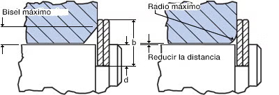
Maximum Chamfer = .375 (b-d)
Maximum Radius = .5 (b-d)
Nomenclature
b = Radial wall (in)
d = Groove depth (in)
| Shaft or Housing Diameter | Maximum Radius on Groove Bottom |
| 1 inch and under | .005 Max |
| over 1 inch | .010 Max |
To assure maximum load capacity it is essential to have square corners on the groove and retained components. Additionally, retained components must always be square to the ring groove in order to maintain a uniform concentric load against the retained part. The radius at the bottom of the groove should be no larger than the table states.
Ring grooves located near the end of a shaft or housing should have an adequate edge margin to maximize strength. Shear and bending loads should be checked and the larger value selected for the edge margin. As a general rule, the minimum edge margin may be approximated by a value of 3 times the groove depth.
Nomenclature
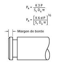
z = Edge margin (in)
P = Load (lb)
DG= Groove diameter (in)
SY = Yield strength of groove material (psi)
d = Groove depth (in)
K = Safety factor (3 recommended)
RPM Capacity
Any retaining ring operating on a rotating shaft is limited by centrifugal forces, including Smalley Retaining Rings. Failure happens when these centrifugal forces are great enough to expand and lift the retaining ring from the groove. With more and more applications requiring higher rotational capacities, Smalley has and continues to invest in ongoing research and development for this area.
A custom retaining ring, or possibly a self-locking ring, may be an option if your application requirements exceed the recommended rotational capacity of our standard ring. Balanced rings are also available in applications where balance is critical.
The self-locking feature consists of a tab and a slot that interlock to prevent the ring from expanding. The tab lines up with a slot on the mating turn such that when the ring is installed into the groove, the tab seats inside the slot allowing the ring to properly function at speeds far exceeding the rotational capacity of a standard retaining ring.
The self-locking feature makes it possible for the ring to operate at high speeds, withstand vibration, function under rapid acceleration, and absorb a degree of impact loading. Read more about a self-locking ring.
As the market leader for innovative retaining ring solutions, Smalley has been continually investing in ongoing research and development to meet the demand for high RPM requirements.
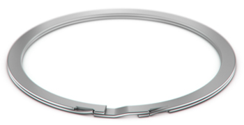
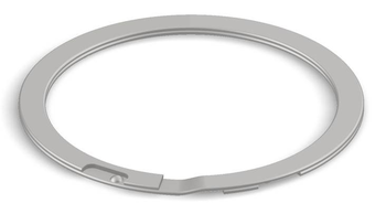
Smalley’s latest retaining ring innovation is the Revolox Self-Locking Ring. The revolutionary self-locking feature consists of a dome-shaped protrusion design that safely and efficiently secures your application at high speeds.
The dome feature is punched into the underside of the ring. The slot portion is created by cutting into the mating turn. The dome is located such that it is trapped within the slot once the ring is installed in a groove, thus locking into place. As the ring rotates it expands, engaging the dome and the slot and preventing any further expansion.
Test results have shown significantly higher RPM capacity over an equivalent non-locking retaining ring. In addition, the revolutionary design is the first high-RPM ring on the market designed with automated installation in mind. This helps make the Revolox an excellent solution for high production volumes.
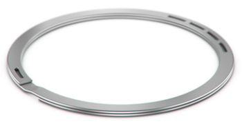
Smalley’s balance feature statically balances the retaining ring. A series of slots, opposite the gap end, are placed such that the ring's center of gravity is statically balanced along its axis of rotation. This characteristic is very useful when the balance of the assembly is critical, such as a rotor. Read more about a balanced ring.
Installation Stress Analysis
The equations provided are used to check that the elastic stress limit of the ring material is not exceeded by stress due to installation. Standard parts that are assembled manually in the recommended shaft/bore and groove diameters do not require stress analysis. Custom rings, or rings being assembled with custom tooling, require stress analysis.
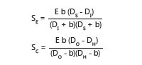
To select a safe stress value, it is necessary to estimate the elastic limit of the raw material. The minimum tensile strength, as shown in the materials table hyperlink of the catalog, can be used as a suitable estimate. As with any theoretical calculation, a closer analysis of the actual application may reveal that these stress values can be exceeded. However, consideration must be made to functional characteristics such as installation method, the number of times the ring will be installed and removed, thrust load, and/or centrifugal capacity.
After forming, the ring’s natural tendency is to return to its original state. This places the inner edge of the radial wall in residual tension and the outer edge in residual compression. To account for the residual stress in the ring when expansion is taking place, only 80% of the minimum tensile strength should be used to compare to the installation stress; see the table below. In custom designs, where the installation stress exceeds the material’s elastic limit, rings can be produced to diameters which will yield a predetermined amount during assembly. Once installed, the ring will have the proper cling on the groove.
Application Percent Minimum Tensile StrengthShaft80%Housing100%
Nomenclature
SE = Stress due to expansion (psi)
SC = Stress due to compression (psi)
E = Modulus of elasticity (psi)
b = Radial wall (in)
DS = Shaft diameter (in)
DH = Housing Diameter (in)
DI = Free inside diameter, minimum (in)
DO = Free outside diameter, maximum (in)